This hack turns a "hobby servo" motor that has been modified for continuous rotation back into a real servo motor with speed feedback.This gives you the ability to control the travel and turning behavior of a small robot with much greater accuracy at any speed. With this mechanism you get 44 pulses per rotation of the motor output shaft, which works out to about 2 pulses per centimeter when using the wheels made for these motors. The pulses have a period of about 20ms at the fastest motor speed. It is designed specifically for the GWServo S03N2BB motor sold by junun.org for the Mark III mini-sumo robot, but from eye-balling photos of other motors I suspect that the same approach will work with many small 20x40mm face Futaba-type hobby servos.
The motors and wheels I used are available as the
Standard-torque
Ball-bearing Servo Motor and Injection Molded Wheels
from:
http://www.junun.org/MarkIII/Store.jsp
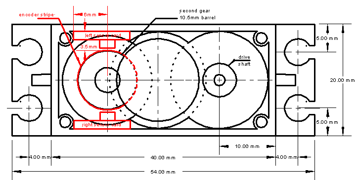
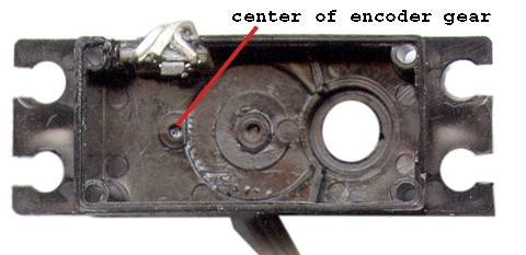
Unfortunately, after these motors are modified for continious rotation they are no longer servos and their speed is not very reliable, especially at low values. The key to fixing this is to get a small led/sensor unit mounted inside the motor and focused on an encoder stripe that is attached to one of the intermediate drive gears (which conveniently enough has a barrel with a 33mm circumference). Note that only one sensor is used, but it can be placed on either side of the case.
HS Motor Gear
Train and Modifications (click for larger image)
click here for a DXF
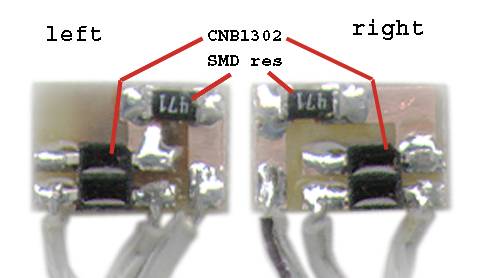
The encoder sensor is a Panasonic CNB1302. It needs to be placed within 1mm of the encoder stripe and have three wires attached to go to the rest of the world. It has an LED built in, but needs an external current-limit resistor. YMMV on how you deal with this...
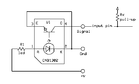
The LED resistor value will vary according to your conditions. With an ATMEGA128 running at 3.3v I used 470 ohms. For a PIC 18Fxxx running at 5v I used 330 ohms. In both cases the sensor load was the controller's Rx internal pull-up, for the ATMEGA about 38Kohms and the PIC at about 20 Kohms. Some experimentation may be necessary to determine your optimal pullup and LED resistors.
The parts I used came from DigiKey:
CNB1302
CNB13020S-ND
470ohm res 541-470ECT-ND
(1/4w 5% 1206 SMD) OR
330ohm res 541-330ECT-ND
(1/4w 5% 1206 SMD)
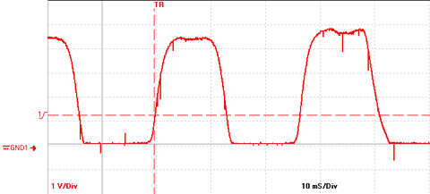
An example Oscope trace of a
working sensor is shown (the motor was running at about .8 revs/sec and
the pulse timing is about 27ms).
Scope Trace
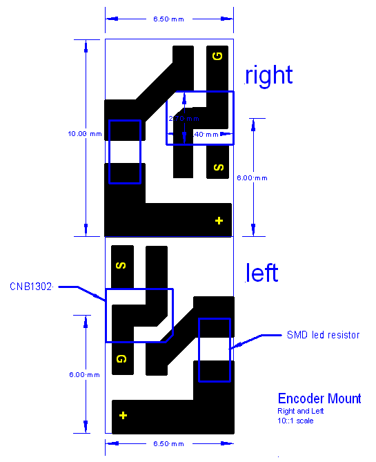
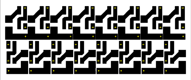
For my part, I laid out a tiny circuit card for the sensor and an SMD LED-resistor. The card makes soldering and connecting the surface mount parts somewhat easier, but its main advantage is that it positions the sensor correctly (if it is cut to the right size and mounted in the right place, anyway). Standard printed circuit material is 1/16" thick, which works out almost perfectly for spacing the sensor vis the 10.5mm diameter gear barrel. The dimensions of my motors' internals are shown above and will hopefully match the motors you have.
Circuit Card
Layout
click image for big version
click here for DXF
version
To make these cards I got a photo-etching kit from Electronix Express
and
laser printed the reduced and step-repeat patterns on a piece of mylar
film (300dpi printable version here,
you may need to mirror the image to get it on the right side of the
film). Then I cut them up with my sheet metal brake and sanded the
edges
to the right size. It is entirely
possible that you could have them made by a commercial PC board house,
one
advantage of the commercial route is that you can have holes drilled
for the connecting wires.
Another option is to use pre-drilled and plated-through-hole prototyping boards, but they will be harder to get to the right size since they are all on .1" spacings. The critical measurements are the height to the sensor from the top of the motor lid and the distance from the corner.
In any case the boards are really tiny and annoying to work with. I stick them down to my bench with a piece of sticky-side up Duc tape, hold the parts with a small hemostat, and solder with the smallest tip (.8mm) that I can find. Search around on the web for advice on SMD assembly if you've never tried it.
Note that there are Right and Left facing versions
of the card
to fit on either side of the motor case as needed. If you have two
motors in a robot they are probably mounted in some kind of mirror
image fashion so you'll want the wires to come out of the box on
opposite sides of each motor.
Also note that the connecting wires are in a different order on each
board, sorry, but that's the way they came out.
Assemble the sensor and your resistor of choice as shown. Note that the CNB1302 is mounted with it's notched corner towards the middle of the board and should line up with the board edge and traces in order to be positioned correctly. Try to get it solidly seated on the board as vertical spacing may be critical. Attach the connecting wires to the outside edge. Be careful to minimize the room that these wires take because they may interfere with the gear under the encoder stripe. Look ahead to the final motor assembly photo to get an idea of what this means...
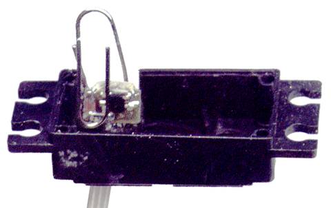
Modifying these motors for continuous rotation involves removing the front cover, hacking off a little nubbin of plastic that forms a stop, and tossing out the bracket that connects the drive shaft to an internal potentiometer. The pot in question provided the "servo" feedback when the motor was used to move to a specified angle. When it is disconnected and adjusted appropriately the motor rotates freely at a speed and direction determined by a pulse width modulated input signal.
The instructions for making the continuous rotation modification are here:
http://www.junun.org/MarkIII/Manual/Appendix.jsp#Servos
or a slightly different approach (Note that this page also has a brief description of how the motors work if you are trying to figure out pulse-width to speed issues):
http://www.junun.org/MarkIII/Manual/kevin/servohack.html
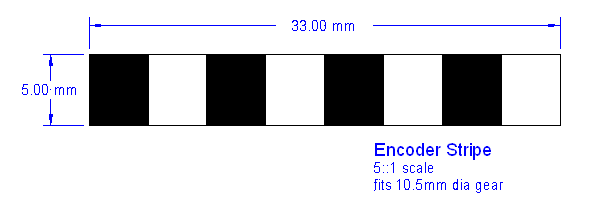
Encoder Stripe
click here for DXF
version
I
used bright white sticky
address labels Avery
"WeatherProof White Labels" #15510 from my
fiendish local Office Depot. The measurements shown on the drawing are
to fit the second gear of the motor. I cut them slightly longer than
the length at both ends so there is a bit of overlap when wrapped
around the gear barrel.
Here is a 300dpi image of a set of them with cutlines, perhaps
positioned to print correctly on the 1x2-5/8" labels specified above: StripePrint. They have a bit of
leader on each end to make a good overlap.
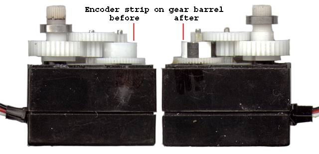
Motor and Gears
Clean all the grease off the gear with rubbing alcohol or brake cleaner or something even worse. Then rough-up the gear barrel surface with an emery board or small file so the label will have something to stick to. Then clean everything again and don't touch the barrel surface. Wrap the cut label strip, starting with the white block, around the barrel. Be careful to keep it aligned with the gear so it goes on straight with no crinkles of bubbles. The last black block should overlap the starting edge just slightly. Then carefully burnish the label down with a piece of smooth hard plastic. (...I just happen to have an old press-type burnishing tool for the job, that shows my age I guess...). I also put a small drop of super-glue on the joined edges in the hope that this will hold them together, I have no idea, yet, how long these labels will stick to the un-sticky nylon gear.
Put the gear train back together the way it was and
make sure there is clearance for the stripe as it rotates. During
reassembly you can also put a little lube on the gears and bearings
(you can get the expensive stuff from junun, or go to an auto parts
store and get some SilGlide or other silicon lube). But be sparing so
it doesn't get all over the stripe after the motor has run for a while.
Cut out a notch in the appropriate side of the motor casing lid. The notch should be about 4.7mm(.185") deep and 10mm(.400") wide starting at the inside edge of the bolt hole as shown (or 14.6mm(.575") from the outside of the lid). Use a jewler's or other fine toothed saw, just clipping the box with your diagonal cutters will crack the plastic. Once the sides are cut you can use a knife or scribe to score the bottom and break it out with pliers. File or otherwise deburr the sharp edges.
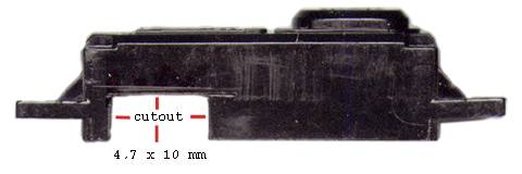
Lid Cutout
As far as I can tell Goop (extra sticky silly-seal) is the only thing that works on everything involved. So put a tiny glob of it on the lid where the circuit card will go and stick the board firmly in the cutout corner of the lid. Note that the sensor should be directly across from the bearing hole of the newly encoder-strip-ized gear. Fold the wires back as far as they can go and clamp the board down with a paper clip until the Goop sets. Make sure it is seated into the corner of the lid before it sets up.
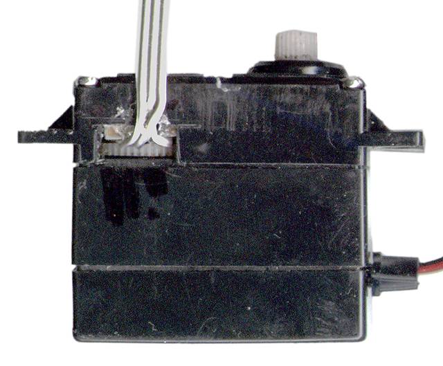
Assembled Lid & Card
Once
everything is set you can reassemble
the motor lid and see if the gear cuts up the wires or it makes awful
noises.
After it's all over I try to re-seal the hole in the case with a layer
of electrical tape on either side of the cable to the motor. This might
work. Or not...
You're on your own here unfortunately. I use these with an ATMEGA128 Mica2 mote card from Xbow.com and my software is written for the TinyOS "operating system" that runs on these cards. If that's your thing, then get this ZIP1... An updated version benefitting from the "Calculus Addenda" below is here: ZIP2.
Otherwise some pseudo-code is all I can do for you: You want to keep track of both the pulse-width and
the number of pulses you get. The pulse-width (period between
rising edges, in, say, milli-sec) is directly related to the speed of
the
motor; a longer period is a slower speed, and v-versa. The number of
pulses is directly related to the distance traveled; as stated before
there are 44 pulses per output shaft rotation. Since the pulses from
the encoder are
around 20ms at the highest speed of the motor, and you should know the
travel of whatever is attached to the motors, i.e., circumference of
the robot wheels, this will give you a way to monitor the speed while
running, and to know how far you've traveled when you're done.
You could do the pulse width measurement with interrupts, but lets just assume that you sample the input every milli-second and count the number of samples between rising edges. Before starting, calculate the number of milli-sec (N_ms) between pulses for the motor speed that you want and the number of pulses for the distance (D_pulse) you want to travel. For instance with the given wheels, to travel 1 meter at 20 cm/sec you want a 25ms pulse-width and 200 pulses of travel (just for grins, if you are running these motors on around 8-9 vots, this comes out to a final drive pulse of about 1.7ms for CCW and 1.3 for CW rotation).
Note: A smaller speed_count indicates that the motor is running FASTER because it is the time between stripes on the gear and a shorter time is a quicker rotation. So the speed_count comparison logic is reversed from what one would think, without thinking.