USBPIC Board and Software
M.Schippling 09/14/2012 v1.0
overview
Hardware
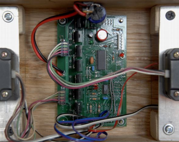
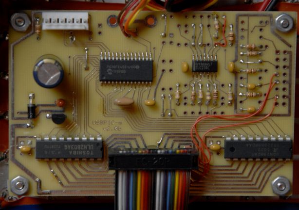
The USBPIC board is a single board micro-controller with
additional power, input, and output conditioning. It uses the
PIC18F2455
series of controllers and has (so far) three optional output
configurations:
- TRANS: Eight TO220 FET open drain drivers;
- MATRIX: Sixteen medium power drivers, using ULN2803 or
UDN2982 chips;
- HBSW: Four TO220 FETs and one L298 (2-channel) H-bridge
chip.
The
input conditioning consists of a quad single supply OpAmp, LM324,
TLC274, etc connected to the first four ADC inputs of the controller.
Multiple OpAmp configurations are supported with many resistor and
capacitor mounting locations. All resistors are 1/6W size to conserve
space.
Both
the CPU and the OpAmp are SOIC packages, which combine a small(ish)
footprint with the possibility that they can be handled and soldered by
normal human beings.
Power regulation consists of a LM78{L}05 regulator and filter
capacitors.
The
board supports USB I/O with an optional B-style connector and In
Circuit Serial
Programming (ICSP) with a connector that matches the
MicroChip PICkit-2 programmer. Depending on the wiring and
configuration all PIC I/O pins are available on external connectors.
The
board is 2.5x3.8". It is laid out using the (proprietary) ExpressPCB
software and can be fabricated by them (for about $60 for three boards
without silk-screen or solder mask). They provide free schematic and
layout software here.
You are pretty much on your own
for op-amp configuration and board assembly...My only advice is to use
a grounded soldering iron, connect and ground the minus supply line
first, and then solder (I recommend the smallest solder -- .015" -- you
can find) the MOSFET devices onto the board -- I have
managed to blow out pins on the chips if the board AND iron are not
grounded together...
Software
My small non-pre-emptive multi-tasking "operating system" is available
for
use with this series of controllers. It is highly
user-configurable and supports timer "tick" and ADC interrupts. It has
a timer based round-robin scheduler which can execute user code at
specified times. It also supports serial USB communication with a host
controller. Configuration is accomplished using a compile time header
file "appconfig.h" which is included by most of the OS files when
building an application. Demo applications are available for each board
type.
It uses the MCC18 C Compiler and tools freely
available
from MicroChip and has been written using the cygwin/gnu tool set under
Windows XP. (Most likely it works under Linux or other systems as well,
but YMMV).
Examples...
Some stuff I've built with these:
A
version 1 TRANS board -- when I still thought that I could use Eagle
without actually killing myself -- running two small stepper motors to
operate The Plumber's Nightmare. Also used in Another Albert, the Anti-Santa Fe Device, and most recently, We Are Experiencing Some Turbulence.
The MATRIX board, using the USB lines as data input's instead, running an 8x8 LED matrix in AGON Box, which is a version of Random Neural Fireflies.
I have used the HBSW board once so far but it is buried in the framework so no photos...
Get it all
Documentation and hardware files (as listed here): USBPICdoc.zip
The source code bolus (see example applications for each board in the
*app directories): USBPICcode.zip
Java host communication package: JavaCommCode.zip
details
General hardware documentation
I/O pin assignments for all board types: PICpins_V3.txt
Parts list with (some) digikey part number: PartsList.txt
Dimensions of board, this is specifically the HBSW board but generally
matches the others: USBPIC_dimensions.png
(Yes the whole OpAmp thing is
confusing, but it can do just about everything I could think of -- it's
best to breadboard your circuit and then figure out which part
positions work for you. Here are some suggestions and supporting files:)
Examples of OpAmp schematics for various uses: OpampSchematic.png
Larger
version of the OpAmp layout positions: OpampLayout.png
ExpressPCB OpAmp schematics: USBPIC_opamps.sch
ExpressPCB OpAmp layout: USBPIC_opamps.pcb
TRANS board
The
FETs on this board can switch multi-amp DC thingies like motors or
lamps -- check the specs of the devices you select -- and can
be
pulse width modulated. The ground bus is laid out such that you can
solder a solid wire along the connection points for each transistor in
order to not have 32 amps flowing through the circuit board trace.
Doing this, with a good heat sink, I have run eight 2.5A devices
without
trouble.
Schematic image: USBPIC_trans_schematic.png
Layout image: USBPIC_trans_layout.png
ExpressPCB schematic file: USBPIC_trans.sch
ExpressPCB layout file: USBPIC_trans.pcb
MATRIX board
The
MATRIX board was developed to run an 8x8 matrix of LEDs. The output
chips are speced at around 50v at .25A per switch. I
would
suspect over-heating if they are all run at that level simultaneously,
but they can run largish LEDs, and smallish stepper motors or relays
without trouble. Unfortunately the UDN2982 pull-up chip that I used is
no longer available in the DIP package needed for this layout (someone
who would like to modify the layout for SOIC chips might find it a
highly rewarding task). The the output chip positions have selectable
power connections at their bypass capacitors in order to allow for
either type of chip to be used in each location (because the chip's
designers thought it would be a good idea to reverse the power pins vis
each type of chip), so the board, as it stands can support two ULN2803
pull-down chips for 16 output lines.
Schematic image: USBPIC_matrix_schematic.png
Layout image: USBPIC_matrix_layout.png
ExpressPCB schematic file: USBPIC_matrix.sch
ExpressPCB layout file: USBPIC_matrix.pcb
If
you happen to be interested in running one of those 8x8 matrix LED
displays that seems to be in every hack-a-thing, here's my
daughterboard for the MATRIX controller:
ExpressPCB schematic file: 8x8matrix.sch
ExpressPCB layout file: 8x8matrix.pcb
HBSW board
The
HBSW board is a hybrid of the TRANS board with an L298 H-bridge chip
replacing four of the transistors. The L298 can run two bidirectional
DC motors at up to 46v at 2A each. Again I would suspect overheating if
run full out, so YMMV. Adding extra copper to the power buses is
advisable for high power use, but it's a little more awkward than the
TRANS board. The L298 specs shotky diodes for the output clamps but I
have used regular 1A rectifiers without incident. The board is laid out
such that all the output devices can be bolted to one heat sink bar
across the middle of the board. The L298 is set up to use current
sensing resistors (R7, R8) on each motor ground if desired. These can
be jumpered to two of the ADC inputs: if you use a .1 ohm resistor and
an opamp gain of about 19 you will get a good range on the ADC for a
maximum 2Amp motor current.
Schematic image: USBPIC_hbsw_schematic.png
Layout image: USBPIC_hbsw_layout.png
ExpressPCB schematic file: USBPIC_hbsw.sch
ExpressPCB layout file: USBPIC_hbsw.pcb
Software
The Ur Document: Design.txt
Schematic block diagram of application code: codeLayout.gif
Relationship of source files and directories: sourceFiles.gif
Specifics of the USB Serial Comm message structure and use: MessageDoc.txt
List of functions and their arguments: FunctionList.txt
The source code bolus (see example applications for each board in the
*app directories): USBPICcode.zip
Once
you download and unzip everything you need to set the location of the
MicroChip MCC18 compiler in src/system/Makefile.inc. Then have a look
at the demo application files in, e.g., src/transapp. The Makefile in
that directory will specify where the system files are, the type of PIC
you are using, and the local files you wish to include. Then the
appconfig.h file has a confusing plethora of options to be defined and
selected to control the size and behavior of the application and OS
code.
Host Communication
I have a pile of Java code that is derived from the UCB,etal
tinyos
Sensor Net project. It runs on a Windows XP host machine and can
(sometimes) send and receive USB messages from the USBPIC device. Get
the whole thing here. See the host/doc/UPComm.txt file for more
information:
Java host communication package: JavaCommCode.zip
license and warranty
Michael Schippling has put all of this in the public domain to be used as seen
fit by those of the public in this domain. No warranty of suitability
or functionality is -- or will be -- provided. You Are In a Maze of
Twisty Passages. On Your Own.
There are three support options:
- None.
- Simple email questions to: usbpic@etantdonnes.com.
Quid Pro Quo
will be observed, i.e., if you help me, I'll help you. I will
appreciate any constructive comment and additions to this tool set, but
I may not include them in the set as given.
- Consulting Contract: I charge $100/hour plus expenses.