a full scale photograph can be found here.
a full scale photograph can be found
here.
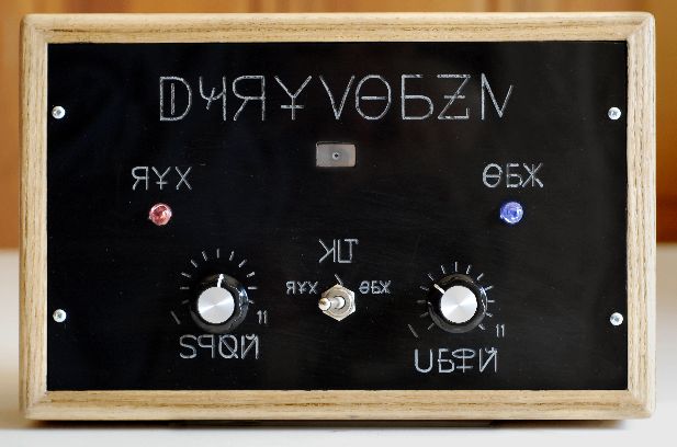
The only known example of this device was discovered just southeast of Santa Fe New Mexico in late February of 2012. It appears to be of terrestrial origin and is perhaps hand constructed -- signs of mass manufacturing consistency are not apparent. It also appears to be some sort of scientific testing device but the labeling of the controls is in an unknown language.
The box is approximately 28cm wide x 18cm high x 8cm deep with the control panel inset in one face. There are two connectors on the right hand side. We have determined that the smaller one is for power and other is a serial data port. We have managed to power the device and reverse engineer the data protocol but, as with its actual function, we are not exactly sure what the data means.
The control panel comprises two dials that rotate through about 270 degrees with positioning tick marks on the face plate. Centered between the dials is a three position toggle switch. Above the controls there are two visual indicators, red on the left and blue on the right, with one auditory indicator centered between them. In operation each indicator flashes or clicks very briefly but continuously.
By operating the toggle switch when the device is powered up we have determined that it controls which of the visual indicators is connected to the auditory indicator. This was done by a careful analysis of the synchronicity of indicator flashes and clicks in each possible position. As might be guessed from the labeling, the left visual indicator is connected when the switch is to the left and the right with the switch to the right. The center position is neither, or silent. The logic of this layout is clearly similar to Western-European standards but we don't yet know if this is by accident or design.
The left control dial sets the speed of both indicators' flashing. The red responds fairly quickly to changes and seems to flash at random intervals -- we have not collected enough data to make a full determination. The blue response lags somewhat. The right dial controls the timing of blue flashes but has no effect on the red. When the right dial is rotated fully counter-clockwise the blue flashes are a regular equally-spaced pattern. When fully clockwise the blue is quite irregular but still has a distinguishable pattern when analyzed. The right dial also functions as a power switch, turning on the device when it is pulled out slightly -- this bears striking similarity to mid-twentieth century consumer equipment. See the Data Analysis section below for more on the flash patterns.
Careful examination of the positioning of the labels and tick marks on the two dials shows that the left set is offset upwards in relation to the centering of the dial. There has been some discussion in our group as to possible interpretations. One of us (Badbunny) argues that it indicates that the scale of the control's operation is non-linear -- which it seems to be. Another (Smith) believes that it was a manufacturing error -- which would indicate that this device is either a prototype or perhaps unique. The main author believes that there is not enough information to decide.
As mentioned, the language of the labels are completely unknown to our linguistic experts. While the characters bear some resemblance to Roman, Greek, and Cyrillic alphabets they could just as well be some sort of pictograms. With such a small sample it is difficult to make an accurate determination or translation. But we can make some inferences from similarities in character and word positioning:
From all of this one might surmise that the device's function is to compare two differently generated data sequences.
We have extracted two data streams from the port on the side of the device. They seem to be relevant to the timing of the flashes of the two visual indicators. We set the left control dial to maximum and the right dial to a one-third position and captured data. By plotting each value against the previous value (a Poincaré plot) it does appear that the red signal is pseudo-random and the blue has a regular pattern, as shown here:
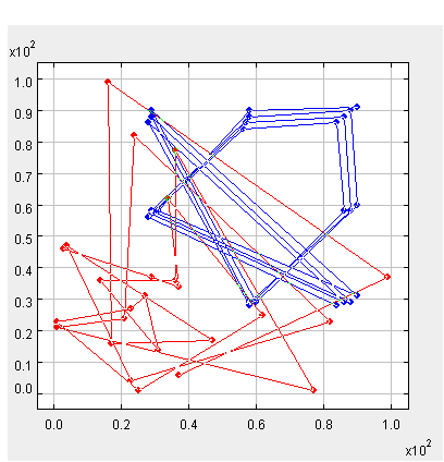
Initial analysis seems to indicate that the red is in fact truely random and that the blue has a pattern that is the ratio of various small prime numbers. However, further study will be required to make any concrete determination.