MicaBOB

break-out board for the Mica Mote 51 pin connector

installed view

So 
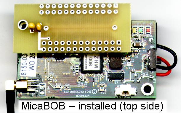
much easier than trying to solder to the Mote board itself...
This is a small double sided circuit board with pads for the Hirose DF9 inter-card connector on the bottom and through holes for two standard 26 pin ribbon headers (or just soldering your own wires). 
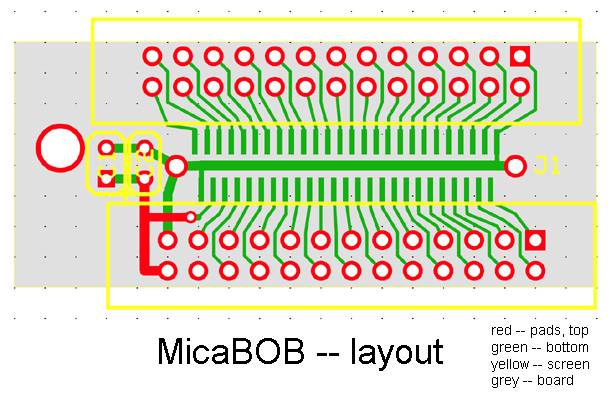
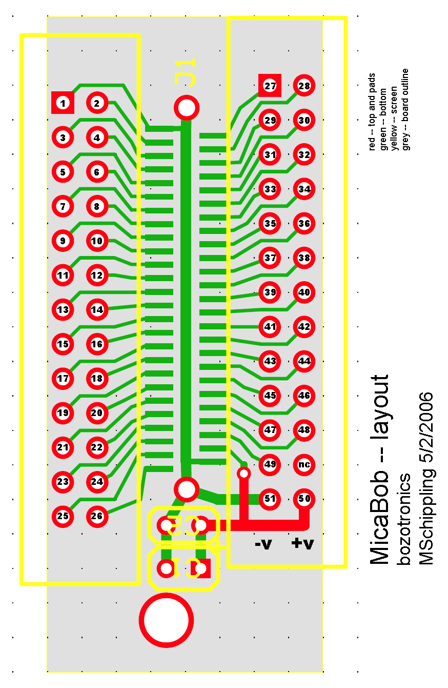
Every pin on the Hirose/Mica connector is brought out to a header pad. There are also pads for two optional bypass capacitors, and a mounting hole which matches up with the Mote-hole nearest the connector.
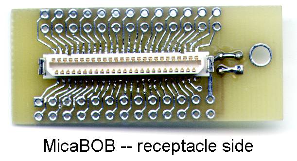
receptacle view

The MicaBOB itself is a .8" x 1.9" doublesided etched and plated-through circuit card made by ExpressPCB ( http://www.expresspcb.com/ ) [who are not cheap, but do a good job]. It was designed by Michael Schippling as an addon to use up some empty space on a card for a separate project, so the size is...what was left over....

Here's a 's a pretty picture of the layout:

small layout

And the big picture for printing: micaBOB_layout.png

Should you wish to produce your own, here's the ExpressPCB proprietary (grrr....) layout data file: micaBOB.pcb
And a mechanical layout in case you want to get measurements (like where the dang mtghole is....):  micaBOB_mech.dxf


Details

You will need a bare board, a  Hirose DF9-51S-1v socket connector that mates with the Micas (available from digikey.com among others), and about 12" of  really tiny solder -- .015" -- that I absolutely must have to make the two into one communicating unit. If you are very good at soldering you may be able to use regular .032" solder but YMMV. I have no plans to make any more of these, unless you want to put in an order for more that about 20 of them...in which case it's probably cheaper to do it yourself.

Assembling and Soldering the connector

The nodules on the back of the DF9 connector fit into the two extra holes in the circuit board so the contact fingers align with the board pads. Notice that one side has fewer fingers than the other, so make sure you put the connector in the correct way around. Using a small soldering iron tip (.8mm is the usual I've found) at a fairly low temperature tack down a pad at each end of the connector and double check that the connector is fully seated on the board. Then solder all the pads. I put the end of the tiny solder on the outward edge of the contact finger and touch the iron briefly to the solder, bringing it down onto the finger. This seems to let a little solder bleed between the finger and the pad on the board. It takes a light touch and good eyes, which is why I don't assemble them for you. When you think you are done look on edge to see if the fingers are really attached, and also check that no solder has shorted the traces to the ribbon connector pads. If you want to use ribbon connector headers, insert them from the top -- the opposite side from the Hirose connector -- and solder them as you normally would. You are on your own for the bypass capacitors. I use a 4.7µf tantalum (make sure you get the polarity right!) and a .1µf ceramic disc, most likely you don't need them but there they are. Power can be attached to the board where the Gnd and Vcc pins (50 & 51) are broken out, or the regular battery connections can be used. The board can be attached to the Mica using a 1/2" 4-40 machine screw/nut with a .175" (~5mm) spacer in-between.

Questions to: schip@santafe.edu