USB Typewriter Conversion Notes
Michael Schippling Jan 17, 2011
Some details and (possibly constructive)
criticism of the
USB TYPEWRITER(TM) REV 2.4 conversion kit
by JACK ZYLKIN at
usbtypewriter.com
Introduction
The conversion kit in question is available from Jack Zylkin on Etsy.com:
http://www.etsy.com/shop/usbtypewriter
and it's a deal at about $70. The kit contains two circuit cards and
necessary components to add a USB keyboard interface to a mechanical
typewriter. I found that it took about 3 days to do the whole
conversion, including some reverse engineering and redesign time
(detailed in the Complaints Department below) -- J.Z. also sells
completed typewriters for a reasonable labor markup if you are less
inclined to hack. Since the keys available on your selected instrument
may not match up to the extended set on contemporary computer keyboards
some of the modern character set is not available to the USB
Typewriter user, but most of what you need is there. Aside from a few
quibbles at the end of this page this is an excellently weird project
to undertake...
If you know how to assemble and solder circuit boards you should have no trouble building the cards. Download the Design Files
from the usbtypewriter.com site to get a look at the schematic and
layout. Assembly instructions are also on the site. Just follow the
schematic and put the named components in the locations indicated by
the silkscreen on the boards -- you will need the schematic to figure
out the appropriate resistor component values. Once assembled, test the
thing by plugging in the controller chip and USB cable and initiating
the calibration procedure as described.
A
caution that may not be necessary: I would leave the controller chip
out of the socket and in some nice static free container when doing
anything but actually USING the keyboard. My experience with other
controller chips and FET input op-amps indicates that they can be
destroyed by inappropriately grounded soldering irons and whanging
around in noisy environments. The Atmega used here may be an exception,
but why take chances?
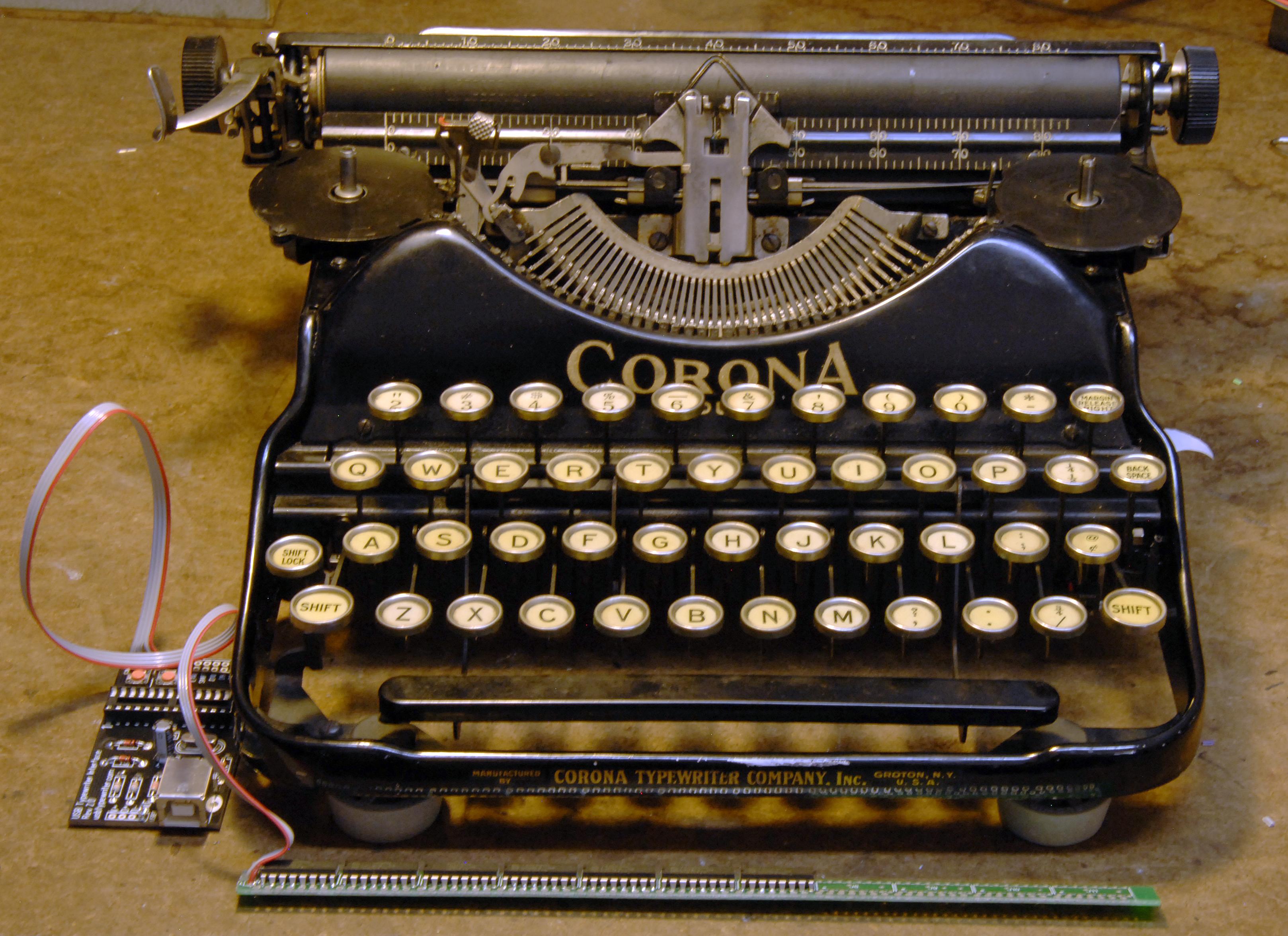
Here's what I had to start with before installation (note: use "View Image" on photo files for much larger versions):
Installation
Installing
the boards and, more importantly, all the switch contacts necessary is
an exercise in inventiveness. How you go about it will depend on the
actual typewriter you have to deal with. Unfortunately this is the
weakest part of the online instructions, so I'm going to give you the
benefit(?) of my experience here. I'm sorry to report that
this is the most intimate I have been with a mechanical typewriter even
though I'm old enough to have written all my college papers on one, so
my knowledge of typewriter nomenclature is less than limited. Thus I'm
going to make it up as I go along.
Key Contacts
The main
labor-intensive component of the USB Typewriter is making and
installing the key contact switches. J.Z. invented a method involving
hammering resistor leads and sticking them on a cross-bar one by one --
which is why the kit contains a bunch of (in my case) 100 ohm resistors
to be sacrificed. This seemed like a PIA to me so I looked for a
"easier" solution.
Fortunately, my Corona Four portable
typewriter had a spring-loaded plate underneath all the key
connecting-rods, and each key-rod had a nice little nubbin that
contacted the plate. The nubbins were clear of the plate when the keys
were not pressed.
Nubbins, a perfect place for the switch contacts:
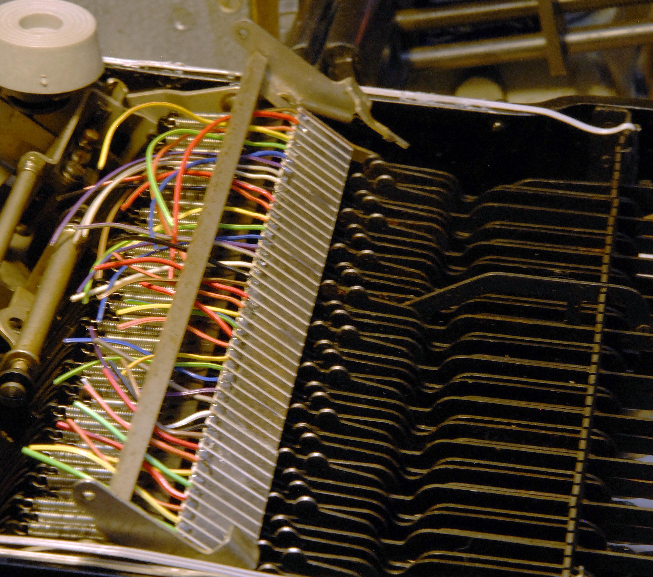
Through
some trial and error measurement procedures I found that my keys were
.188 inch apart. I layed out a circuit board with contact strips on
that spacing which could be glued to the spring-plate. A contact strip
gets hit by a key-nubbin when a key is pressed with a slight
wiping motion so it should make a good contact. It remains to be seen
how long the contacts will last since they are just thin copper with a
layer of solder tinning applied. In any case the strip you see in the
photo is about 8.5" long and .75" wide, with the rainbow colored wires
soldered on the edge out of the way of the nubbins. The contact board
is glued to the spring-plate using Goop (very sticky silicone sealant),
which I used on the wiring elsewhere, and greatly prefer to hot-melt
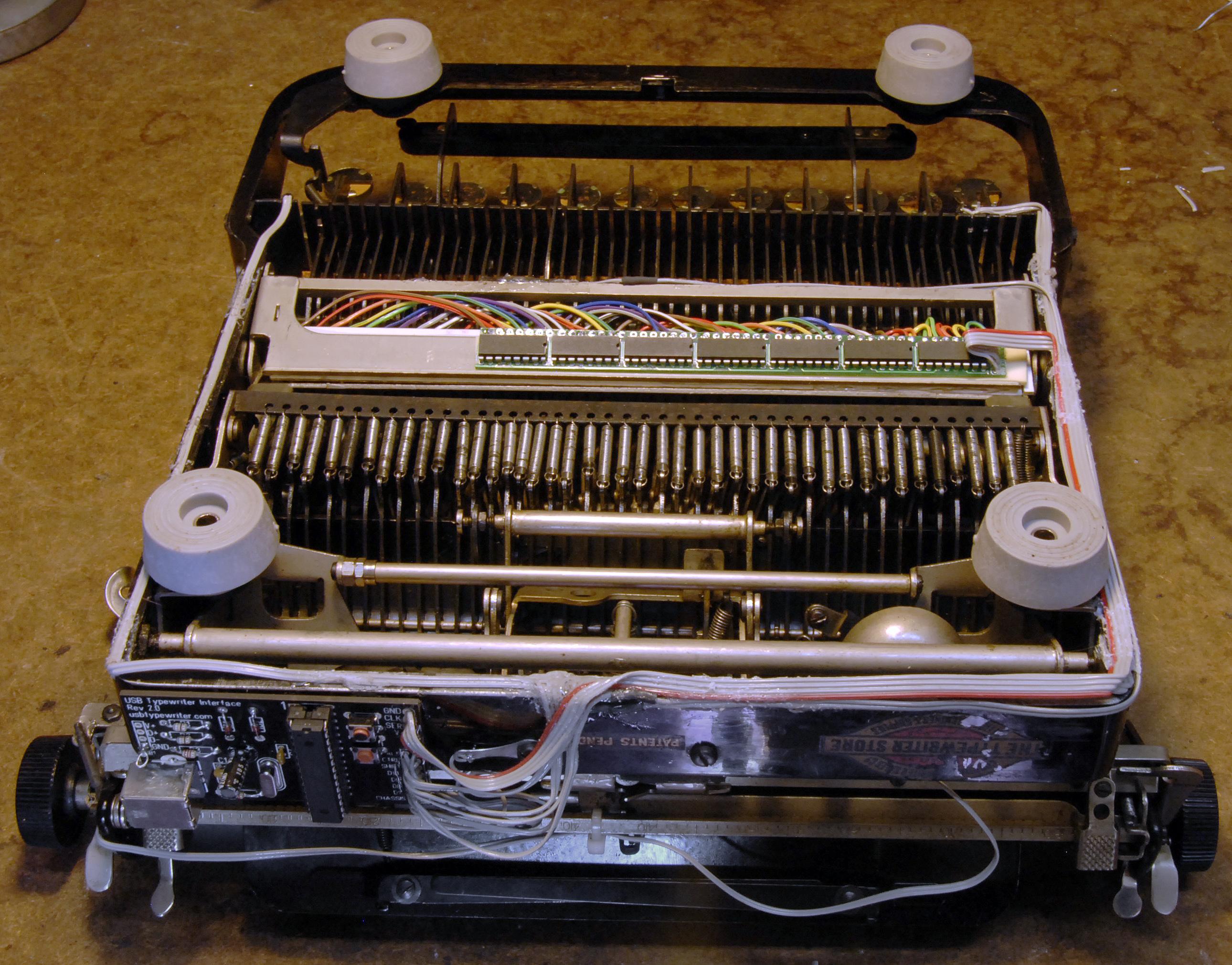
glue. When complete, the whole assembly is flipped over to the right
and mounted as seen in the last photo on this page.
An image of the contact board layout is here.
I used a laser printer to make an iron-on mask and then cut strips from
the board after it was etched. I found that I had to diddle with the
DPI setting of the image (using PhotoShop) until I got the contact
strips to match up to reality, by repeatedly printing on regular paper
and holding it up to the nubbins for comparison. If your keys are on a
different spacing you will have to do more diddling to scale the image
correctly.
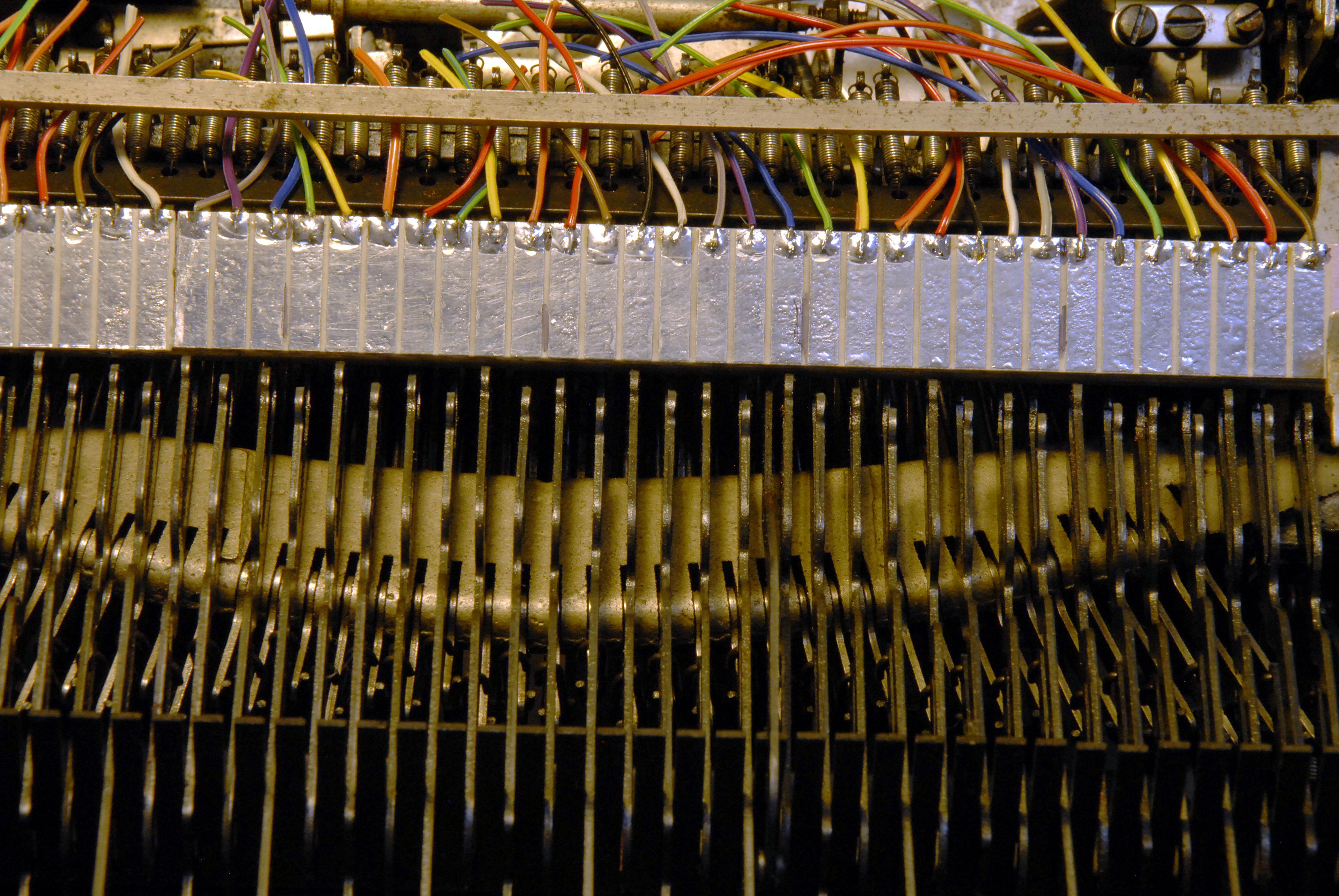
Here's a picture of how the contacts and nubbins line up before assembly:
Also note that there are many more shift-register chips on the Sensor Board
than necessary, which is why you can cut it to length. It doesn't
matter which inputs (outputs actually) you connect to any key-contact
-- you can skip whole chunks if your wiring doesn't reach -- as long as
you have all the chips populated up to the end of your line. The
configuration procedure will sort out what's connected to what.
Other Switches and those "D" inputs
The least clear part of the instructions deals with the non-keyboard-contact switches for which tiny (and very
delicate -- I broke 3 of the supplied 4 before they even got near the
typewriter) reed switches are supplied. You can see the wiring for
these switches on my typewriter in the last image. The reed switches
and magnets need to be mounted near the operational components of keys
which are not on the key-contact strip such as RETURN, SHIFT, SPACE,
and BACKSPACE. Since this is a matter of mechanics and taste I will
leave the details as an exercise for the reader. There are however a
few devils...
I had a lovely place for the SPACE bar sensor at
the back of the typewriter under the carriage, until I got to the final
test and found that this was also the mechanism that moved the carriage
after each character was typed. So I had to move the sensor to a new
location that was directly activated by the space bar itself. The
lesson learned is stay as close to the lever or key as you can since
those old mechanical designers had a buncha tricks up their collective
sleeves.
The thing that is not covered at all is: For what special keys do I need to do this? For some reason CNTL, ALT, and SHIFT keys, if you want to have them available, must
be wired directly to the control board using the reed switch mechanism.
This generally precludes them from being "normal" keyboard keys, unless
you have some tricks not used by those original designers. I got lucky
and was able to put a switch near the last key on the keyboard which
was not used in the final character set: "@-cent", so I could use it as
my CNTL key. YMMV.
This leaves us with a few more
non-key-contact keys or whatnot. Specifically one needs SPACE
and RETURN and probably wants BACKSPACE as well. Unfortunate this
adds up to FIVE reed switches and only FOUR were supplied in the kit.
Plus I had to add a sixth to get my CNTL without overloading my
BACKSPACE. So my list of special keys needing mechanical reed
switches is:
- CNTL: A regular key, disconnected from contact strip, using a required reed switch;
- ALT: A non-key-contact key ...margin release... using a required reed switch;
- SHIFT: A non-key-contact key, using a required reed switch;
- SPACE: A non-key-contact key, using a reed switch, wired to the "D" auxiliary inputs;
- BACKSPACE: A non-key-contact key, using a reed switch, wired to the "D" auxiliary inputs;
- RETURN: The carriage return lever, using a reed switch, wired to the "D" auxiliary inputs.
Two
things your should know about the "D" auxiliary inputs: The first is
that they do indeed "swing both ways" in that the software will detect
if they are normally open or normally closed and behave accordingly, so
no-worries about which way you need to get the switches to work vis
magnets near and far. The second, which is not mentioned, is that they
are included in the regular keyboard scan such that they can be mapped
to any key (except those durn Cntl-Alt-Shifts) during configuration.
Configuration
The program is pretty swell when it comes to configuration. Every key
(except those durn Cntl-Alt-Shifts) gets mapped to it's contact and
then the config is saved for later power up, so it doesn't really
matter what you solder to what (except those durn
Cntl-Alt-Shifts). What isn't mentioned in the documentation is exactly
which keys are to be mapped, so I've included a dump of the
configuration run here.
What I
learned from running the configuration is that there are some keys for
which I didn't have actual hardware to map, and that I did have one
spare key on the contact strip that was not called for in the map
"1/4-1/2" -- which are very pretty but apparently useless to a
computer. So I decided to assign that key to TAB, although it could be
anything.
Also not on my keyboard, and thus mapped to oblivion, were:
- ': note: on upper-8 but not a separate key
- 1: =: \: [: ]: ~:
- delete:
- LEFT: RIGHT: UP: DOWN:
- ESC:
- F01: -- F12:
Another
tidbit not mentioned anywhere and in need of reverse-engineering is
what symbols are mapped when one uses the SHIFT key with numbers and
other punctuation keys. The program goes along pretty much with the
modern computer keyboard's idea of what should be where, which does not
entirely match my typewriter's old-fashioned layout. Here's the list of
mapped upper-case keys (lower upper):
- 2 @
- 3 #
- 4 $
- 5 %
- 6 ^
- 7 &
- 8 *
- 9 (
- 0 )
- - _
- ; :
- , <
- . >
- / ?
A Final Look Under the Hood
The circuit boards are mounted using double-sided foam tape and the wires glued down with Goop:
Complaints
I
can't think of a good reason for the Cntl-Alt-Shift keys to be treated
differently and in need of special inputs -- as you might guess from
reading the foregoing. Perhaps there is a reason, but if there was none
it would make the key-map selection much more straight-forward.
Another
no-good-reason-to-me thing is the use of M74HC595 shift register
chips for the key-contact detection. These are serial-to-parallel
devices and their use here requires that the whole typewriter chassis
be wired to an input pin on the controller. In practice this seems to
work fine, but it would be "better" if the entire case could be
grounded. If that were the case (no pun left un-tended) then the
key-contacts would work just like the D auxiliary switches -- switching
to ground -- and any switch or key could be used in any function. The
74xx165 chip is a parallel-to-serial shift register that could
implement this, however it may need pullup resistors which would
complicate the sensor circuit board.
There's got
to be a better way to do the key-contacts. Instead of rolling my own
contact strip board I suspect I could have used standard .100 spaced
edge-board-contacts and skipped a contact every once in a while while wiring.
In the REV2_0 documentation, the page named
USBTYPE_S2_Schematic.pdf
seems to be a copy in a different color of the
USBTYPE_S2_TOP.pdf file.
An actual schematic is in the REV1_0 bundle,
but has been slightly modified for the 2_0 board.
There are two push-button switches on the REV_02 board, but only one seems to
do anything. The top switch, labeled S1, is the one to use for
configuration.
I needed six reed switches and broke three of the supplied four...
fortunately I have hoards of just about everything arcane.
It would be nice if the upper-case punctuation was mappable
during configuration so it could be made to match older keyboards.