Basic Machine Tool Safety and Use
Michael Schippling
schip@etantdonnes.com
http://www.etantdonnes.com/MACHINE
I. Overview
A five session class with
additional lab periods for one-on-one hands on instruction. In this class
you will learn how to safely operate a lathe and a mill, and how to use
them to make simple objects.
A. What will be covered in the class sessions.
Introduction, Safety, and Planning.
Basic Lathe and Mill operation.
Lab.
More Lathe and Mill details.
Lab.
Measuring.
Lab.
Tooling.
Lab.
B. Rules....Always Rules....
ALWAYS wear eye protection.
ALWAYS securely clamp the work-piece and the cutting tool.
ALWAYS shut off the machine and wait for it to stop
before approaching moving parts.
ALWAYS clean up after yourself.
NEVER leave the chuck key in the chuck.
NEVER wear loose clothing or jewelry when using the tools.
NEVER leave loose objects near moving parts.
NEVER start the machine with the tool in contact with the work.
DOUBLE CHECK YOUR SETUP BEFORE PROCEEDING.
If something doesn't look or sound right
-- ASK FOR ADVICE.
C. Demo of lathe and mill operations.
D. Planning a project.
Drawings: always make
at least a crude sketch of your design in order to figure out the measurements.
Sequence of operations:
think ahead so you always have a way to clamp and measure the workpiece.
Assembly: there may be
a specific order in which your project has to be aligned and assembled.
II. Introduction to the Lathe
The engine lathe is the grown
up cousin of the potter's wheel and more sophisticated sibling of the wood
lathe. All of the above tools spin the material being worked (work-piece)
while holding some sort of tool in contact with it. In the case of the
potters wheel, you use your hands as the tool to form the clay work-piece
into a symmetrical cylinder of some kind. In the case of the engine lathe
the tool is a piece of hardened metal that is securely clamped into a tool
holder and the work-piece is a bit of metal (or wood or plastic) that is
being shaved down into a cylindrical shape. The lathe is used for making
concentric circles and rings (and piles of chips) out of chunks of material.
A. Lathe nomenclature
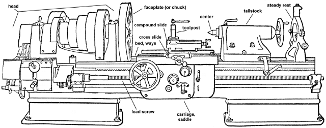
B. Basic Lathe operations
-
Boring -- cutting or drilling a hole into the
center of the work-piece.
-
Turning -- cutting down the outside of the work-piece
to make it a smaller diameter.
-
(sur)Facing -- cutting material off the front
surface of the work-piece to flatten or shape it.
-
Parting -- cutting a thin slice through the
work-piece to cut it off of the rest of the material.
-
Threading -- cutting a spiral screw thread into
the work-piece, either on the outside to make a bolt, or on the inside
to make a nut. An advanced topic.
C. Setup for basic operations
ALWAYS clamp the work-piece and cutting tool SECURELY.
Work and tool holding.
Chucks, faceplates, and other work holders.
Toolposts of various kinds.
Cutting tools: shape, selection, and sharpening.
Cutting speeds and different materials.
Use Coolant liberally, it can't hurt.
Setup using the centering drill in the tailstock.
Make a small centering 'divot' in the workpiece
to catch the drill when it starts.
Using drill bits in the tailstock.
Start small and work your way up with multiple drill
bits.
Keep the drill flutes clear of chips to prevent
breakage.
When done use a scraper to remove burrs from the
edge if necessary.
Using a boring bar. Demo -- this is a (slightly) advanced topic.
Using the live center in the tail stock.
Use the centering drill to make a contact point
for the live center.
Centering the cutting tool.
It should usually be just slightly above center
to avoid running under the work and jamming.
Use a thin piece of sheet metal between the tool
and work to 'eyeball' tool centering.
Removing material.
Start with a light cut to make sure the workpiece
is not off center.
Take multiple 5-10 thousanths cuts using as steady
a feed as you can.
Finish with a couple 1-2 thousanths cuts for a clean
surface.
Use a file to smooth the surface if polishing is
needed.
NOTE: You are cutting the DIAMETER of the workpiece, but the slide
is calibrated for the RADIUS. So when you remove .010" on a pass you have
reduced the diameter by .020"!!!
Cutting to shoulders.
Angle the appropriate tool to get the point into
the corner.
Centering the tool.
It should be pointing towards the workpiece face.
It should be exactly on center or you will get a
little 'nit' in the middle of the workpiece.
Removing material.
Start with a light cut to make sure the workpiece
is not uneven.
Take multiple 5-10 thousands cuts using as steady
a feed as you can.
Finish with a couple 1-2 thousanths cuts for a clean
surface.
Use a file to remove the sharp edge from the end/corner
if necessary.
Setup for the parting blade. It must be exactly SQUARE
to the work-piece and slightly above center.
NOTE: NEVER, EVER use the live center when parting. The part
will jam when it cuts through, just like using the miter and fence at the
same time on a table saw.
Go slowly and use lots of coolant.
Catch the cutoff workpiece when it's finished or it will get
dinged on the lathe bed or carraige.
Demo -- this is a (fairly) advanced topic, but really
cool and why we have lathes to start with.
Use a tool shaped for the thread, use the threading indicator to 'synchronize'
the tool with the workpiece rotation, and make multiple passes over the
thread with decreasing depths.
C. Lathe tool bits
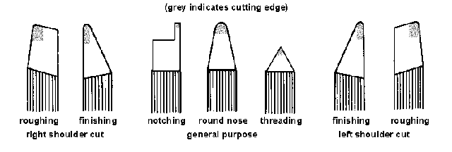
You may find many other special
tool shapes, but these are the basic ones. The general idea is to keep
as much material as possible on the tool's working face, because of the
forces and pressures involved. The general round nose and roughing tools
can take deeper cuts because they are stronger. The finishing tools take
shallower cuts and have a finer contact with the work. The notching and
threading tools should only be used for their specific tasks because they
are fairly weak mechanically.
The left and right shapes
may seem to be named backwards, but the direction refers to the edge of
the workpiece that can be cut, not the direction that the tool points.
Thus, the Left tools are used to cut a shoulder on the left side of the
work and the Right tools on the right side.
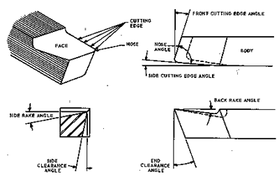
The various faces and angles
of a steel lathe tool bit are shown on the drawing above. Strictly speaking,
different work materials require different angles and clearances, but in
practice a compromise tool can be used for almost all work. Side and edge
angles of 5-10 degrees are usually sufficient. End clearance should be
2-5 degrees in order to keep as much tool material for support of the cutting
edge as possible. The back Rake may be modified for the material being
cut, generally the harder or more brittle the material the less rake:
Metal Being Cut: Cast Iron
Hard Steel/ Brass Carbon Steel Mild Steel
Aluminium
Top Rake Angle:
0°
8°
14°
20°
40°
The lip at the back end of the rake is called a `chip
breaker' because it tends to direct the spiraling cutting (chip) upwards
and break it off before it gets a chance to wrap itself around the tool
and work.
Good instructions for steel
tool grinding can be found at:
Carbide tools are usually
used with a 0 degree rake, and are not so easy to grind anyway....
III. Introduction to the Vertical Mill
The Vertical Milling Machine
is a really fancy drill press. It has a chuck or other mounting device
to hold and spin a cutting tool, and a very heavy duty X-Y table to which
you attach the work-piece. Using the table the work-piece can be positioned
with great accuracy and repeatability. Like drill bits, end mill cutting
tools are usually sharpened on the end so they can drill vertically, but
they are also sharpened on the sides so they can cut horizontally as well.
Therefore, besides being able to drill a hole into the work-piece, the
end mill can cut slots and other shapes, as well as flatten surfaces. The
Vertical Mill can also be used to cut exact angles and curves, and for
many other operations.
Horizontal Milling Machines
are a different type of tool mostly used in production shops. The cutting
tools are mounted on a horizontal arbor, sort of like a table saw, and
the work-piece is moved longitudinally under the cutters. They are good
for cutting slots and grooves, and surfacing material, but are not as versatile
as the Vertical Mill.
A. Mill nomenclature
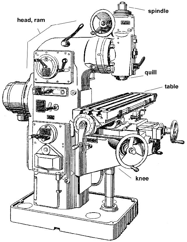
B. Basic Milling operations.
-
Drilling -- drilling holes in the work-piece.
-
Milling -- cutting slots in the work-piece.
-
(sur)Facing -- flattening a surface.
-
Slitting -- cutting a narrow clearance slot.
-
Boring -- like drilling, but usually BIG holes.
Somewhat advanced topic.
C. Setup for basic operations
Work and tool holding.
ALWAYS clamp the work-piece SECURELY.
NEVER try to hold it in your hands or with pliers, etc.
Using the vice to hold work.
Using step blocks to clamp work to the table.
Cutting speeds and different materials.
Use coolant when in doubt....it can't hurt.
NOTE: ALWAYS watch the tool when moving the table.
The one time you forget you will jam the tool into
the vice (or something) and break it off.
Using the drill chuck is just like a drill press,
but better.
Clamp the workpiece however you can.
Position the drill using the table feeds.
Drill the hole. Just like that...
Using collets to hold the end mill cutter.
Larger end mills can be held in the drill chuck
if accuracy is not an issue.
Smaller end mills need to be centered using the
collets.
Use 2-flute end mills for aluminium and soft or
gummy materials and 4-flute end mills for steels.
Drilling into the work-piece.
Most end mills can cut like drills, but if there
is any doubt start with a real drill bit.
Also notice that you can make a nice square-bottom
hole with the end mill.
Moving the work-piece to make a slot or flatten an edge.
Once the end mill is at the right height in the
work piece, use the table feeds to move it.
The rule of thumb is: use only 1/4 of the cutter's
area when slotting, i.e.,
when edgeing
plunge in 1/2 of the cutter length and take off only 1/2 of the its diameter,
or when slotting
plunge in 1/4 of the cutter's diameter.
Feed speed, depending on the material, can be 5-10
thousandths per second
at a cutter
depth of up to 1/2".
Smaller cutters need much lighter feeds to keep
from breaking.
When in doubt, ALWAYS FEED SLOWLY when cutting the work piece.
ALWAYS keep the cutter clear of chips, especially with aluminum which
`gums up'.
NOTE: You can roughly find the edge of the workpiece by slowly moving
it towards the running end mill cutter until you just see a chip being
formed, or use a piece of thin (cigarette?) paper in between the two. Remember
that you have to continue in the same direction for half the cutter's diameter
if you want the mill to be centered directly over the work piece's edge.
Using the end mill on a vertical side.
Just like slot milling but watch for the cutting
direction:
Conventional and Climb cutting...what and how come?
Usually use Conventional milling, feed the work
INTO the cutter so the tool pushes against it.
Using the facing tool on the top of the work-piece.
A larger cutter can be used to make a flat surface.
Slow the machine way down....the facing tool is
effectively 2-3" in diameter.
Using the slitting saw holder.
The blade should be oriented counter-clockwise when
looking at the end of the holder.
Keep the work piece and mounting well clear of the saw blade.
Cutting the slit.
Feed the work into the saw, don't plunge the saw
into the cut.
Generally either milling direction will work fine,
but Climb milling may hold the work better.
ALWAYS keep your hands clear of the saw blade, even when it is not
turning....
Demo -- using a boring head, this is a (somewhat)
advanced topic.
A very nice way to make a hole that is not a standard diameter.
C. Mill Cutting Directions
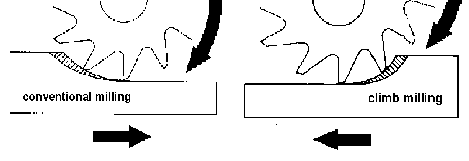
In general you want to use
the Conventional milling cutting direction because it puts the force of
the table feed screw in oppostion to the direction of the cutter. But in
some cases this just can't or shouldn't be done, so you use Climb milling.
The problem with Climb milling is that, as you are pushing the work into
the cutter, the cutter is trying to pull the work along with it, away from
the feed screw. If there is any play in the table feed screw (and there
always is some) the cutter will grab the work and pull the table along
with it. The result will be chatter and a rough finish for the cut. The
advantage of Climb milling is that it pushes the work into the clamping
surface, whereas Conventional milling tends to pull the work up off the
surface. When cutting thin or delicate materials Climb milling may make
clamping the work easier.
IV. Measurement
Accurate measuring is the
crux of good machining. Even in an art project you may find that you need
to make two parts that fit together well. It may be a press-fit, a really
nice smooth feeling fit, or just a loose-fit to weld. In all cases you
have to be able to make repeatable measurements in order to get it to work
right. The simplest measuring tool is the ruler but it is not very accurate
or repeatable so machinists use calipers and micrometers. Squares and other
angle measuring tools are often necessary too. Many other types of measuring
devices with various accuracies and uses are available. Being able to perform
simple numeric calculations is an absolute necessity as well. Measuring
tools are a black hole for money.
B. Using the Basic measuring tools.
1. Ruler and dividers.
2. Calipers: direct, vernier, dial, micrometer, and/or electronic?
3. Dial indicator and magnetic base.
4. Square and center finder.
5. Protractor.
6. Calculator.
C. Practical measuring.
1. Layout.
Ruler, scribe, divider, and center punch.
Using the square and center finder.
Using a divider.
Using a protractor.
2. Common lathe setup and measurements.
Diameter and radius, inside and
outside.
Hole depth.
Centering with a dial indicator.
3. Common mill setup and measurements.
Finding an edge and indexing into
the work-piece.
Aligning the work using a dial
indicator.
4. Other cool tools.
Feeler Gauges.
Bore gauges.
Micrometers.
Test indicator.
Height gauge and surface plate.
Screw gauges, and on and on and on....
A Sine Bar side bar.
D. Reading a vernier scale.
Many measuring devices have
vernier
scales which provide an increased accuracy of one or more decimal places
in their readings. Calipers, height gauges, and micrometers as well as
angular measurement devices all make use of this technique. The vernier
measuring device has two scales. The main scale works just like a ruler.
The second, vernier, scale is used to gain the extra accuracy. It is opposite
the main scale (sort of like a slide rule, if anyone remembers slide rules....)
shorter in length, and is layed out such that 10 divisions on the vernier
take the same amount of space as 19 divisions on the main scale (in the
case of the example below, although the technique holds in any ratio of
vernier to main scales where the vernier has one
less marking than
the main).

To read the vernier device,
the 0-mark on the vernier is used to get the main scale value just like
a regular caliper. Be sure to use the value of the main scale mark that
is just to the left of the vernier zero mark as is shown in the above diagram.
That is, the value is 3 mm, not 4 mm, even though the answer is closer
to 4.
Now look closely at the vernier
scale. Notice that 10 divisions on the vernier match 19 divisions on the
main scale, and that this guarantees that one of the vernier markings will
line up exactly with a mark on the main scale. Decide which vernier mark
comes closest to matching a main scale mark, in our example this is vernier
mark 7. Combine the two readings to give a length of 3.7 mm.
Most SAE (inch) calipers
have main scale markings at every .025 inch and use a vernier scale to
add the last .025 inch of accuracy to measure thousandths (.001) of an
inch. Because of their simplicity, vernier measuring devices are usually
a great deal cheaper than dial or digital devices with the same accuracy,
but they are slower and harder to read. Unfortunately you will probably
run into a vernier at an inopportune time, so it's a good idea to learn
how to use them.
V. Tooling
Tooling is the other black
hole of machining. Tooling may be divided up into two categories, Cutting
and Mounting. Cutting tools are like drill bits, milling cutters, etc.
Mounting tools are like vices, chucks, and various positioning blocks and
fixtures. There is no end to the variety of either that you can find, or
their expense, but you can also make many jigs and holders yourself as
you need them.
A. Common Cutting tools and materials.
Materials -- Carbon Steel, High Speed Steel, Cobalt,
TN coated, Carbide, Diamond
Types -- Drills bits. Center drills. Reamers. Countersinks.
End mills. Saws. Other milling
cutters.
Fly cutters. Boring head
and boring bars.
Lathe tool bits. Knurling.
Taps and Dies for threading.
B. The Mystery of Material Cutting Speeds
Cutting speed is the speed
at the outside edge of the tool as it is cutting. This is known as surface
speed and is measured in surface feet per minute (SFPM). Cutting speeds
depend primarily on the kind of material you are cutting and the kind of
cutting tool you are using.
The harder the work material, the slower the cutting speed. The softer
the material the faster the speed:
Increasing Softness of Material
Higher Speed ----->>>>
The harder the cutting tool, the faster the cutting speed:
Carbon Steel -- High Speed Steel
-- Cobalt Steel -- Carbide
Increasing Hardness of Tool
Higher Speed ----->>>>
With faster Cutting Speeds
and harder materials, more heat is generated. If the tool bit gets too
hot it will loose its sharpness and often become un-useable. You know this
has happened to a piece of tool steel if you can see darkened, burned looking
areas near the cutting tip. Sometimes these can be ground out and the tool
resharpened, but not always. So you need to avoid going too fast. But going
to slow can cause problems too. Higher speeds (and sharper tools) tend
make smoother cuts and leave less finish polishing to do. Also sometimes
the tool chatters on the work and doesn't cut evenly if it is going too
slow. And it just takes longer to do anything if you are cutting slowly.
So compromise is the essence of machining...
Determining Spindle RPM
The Cutting Speed is the
speed that the outer edge of the tool bit travels relative to the work
piece. This should not be confused with the Spindle RPM which is the `speed'
that the tool bit (or work piece in the case of the lathe) rotates. The
Spindle RPM must be set so that the tool will be operating at the correct
Cutting speed. As the diameter of the tool bit increases, the distance
traveled on each rotation also increases because it is `drawing' a larger
circle. This means that the Spindle RPM will have to be lower to compensate:
Increasing diameter of tool or workpiece
Higher tool speed (sfpm) ----->>>>
----->>>> Lower RPM
Therefore, to find the proper
Spindle RPM we need to calculate the number of revolutions per minute which
will cause the outermost edge of the tool to travel at the desired Cutting
Speed. Fortunately there is a quick and dirty Cutting Speed and RPM table
included in this package. But if you ever need to know, here's how you
calculate the correct speed....
The cutting, or surface, speed
changes with the size of the tool. So to keep the cutting speed the same
for each size tool we must use a formula which includes the tool's diameter
to calculate the proper RPM to attain the correct surface cutting footage.
This also applys to the speed of a lathe spindle relative to the stationary
cutting tool:
(Cutting-speed x 12) / (Diameter-in-inches
x Pi)
Which conveniently enough reduces to the
approximately-good-enough:
(Cutting-speed x 4) / Diameter-in-inches
This simplified version of
the RPM formula is the most common formula used in machine shops for all
sorts of machining operations. Put this formula to work in calculating
the RPM for an example drilling operation. Use the recommended cutting
speed of 70 SFPM for mild steel, and a 1/2" High-Speed Steel drill:
Cutting Speed = 70 (fpm)
Diameter of Cutter = 0.500 (inches)
70(fpm) x 4 = 280;
280/.5(inches) = 140
Spindle RPM = 140
Although we have calculated
the RPM, remember that this is only a recommendation. Some judgment must
be made in selecting the actual RPM to use. There are always outside factors
that must go into deciding on the proper speed and feed to use. Ask yourself
these questions before deciding on a spindle speed. How sturdy is my setup?
Go slower for setups, which lack a great deal of rigidity. Am I using coolant?
You may be able to use a faster speed if you are using flood coolant. How
deep am I drilling? If you're drilling a deep hole there is no place for
the heat to go, so you may have to slow the RPM down for deep hole drilling.
See the Cutting Speed Table
for some good rules of thumb and you probably won't ever have to do this
math for yourself.
B. Common Mounting tools and devices.
Vice. Step blocks. V-blocks.
Parallels. 1-2-3 Blocks. Angle plate.
Collets & chucks.
Face plate.
Spin Index. Index Dividing
head.
Appendix
A. References
Note that I have not checked these in many years but the Wayback Machine
might help if they are missing now...
Just in case some one wants to
get the Granite 1324 so I can see what it's really like.
B. Suppliers
phone: 800-645-7270
phone: 800-873-3626
phone: 800-523-4777
phone: 800-423-2567
C. Handy tables


